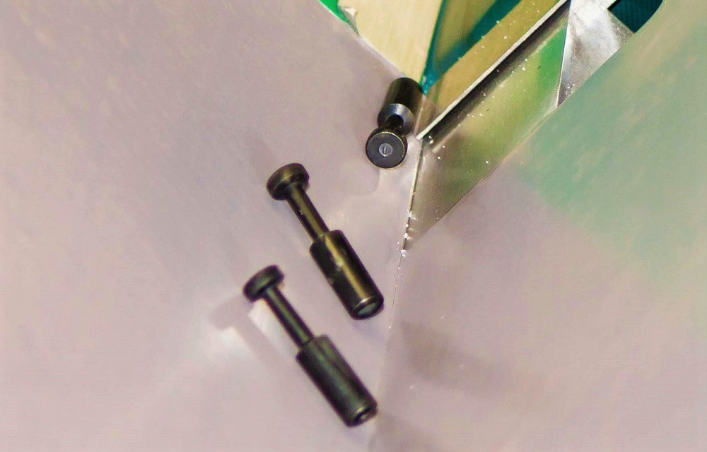
Feeding technology plays a key role in automated assembly. Components, which are often provided unsorted, must be separated and handed over to the actual assembly process in an orderly manner. The task of feeding technology is to meet this challenge, sometimes several hundred times per minute.
In industrial applications, the vibratory bowl feeder (VBF) is often used for this purpose. It is characterized by a simple design and low operating costs. At the same time, VBFs are inflexible, as specific mechanical baffles have to be developed for each component. Even the smallest changes to the components can significantly reduce the performance of an existing VBF.
In order to counteract these deficits of conventional feeding systems, the Institute of Production Systems and Logistics (IFA) has developed the aerodynamic feeding technology. With the help of air – instead of mechanical chicanes – workpieces are fed reliably, quickly and flexibly.
In the current project, which is funded by the German Research Foundation (DFG), the Institute of Assembly Technology (match) is conducting research in cooperation with the IFA to predict component behavior – with the aim of increasing the flexibility and robustness of aerodynamic feeding technology.
How does the "Aero" work?
In aerodynamic feeding technology, the components are oriented with the help of an air jet (see video).
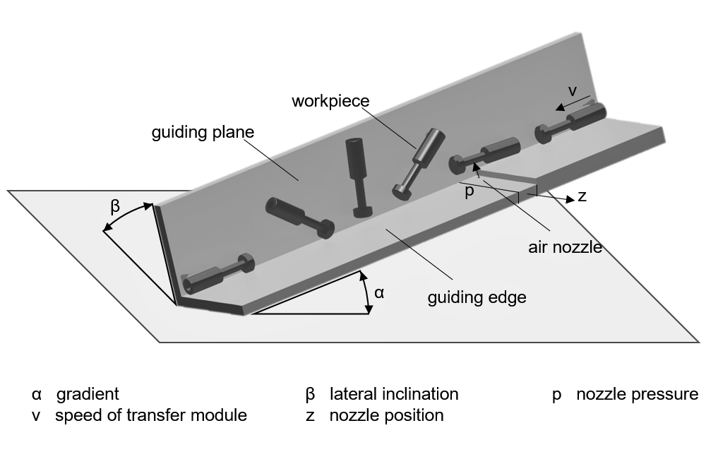
The success of this feeding technique depends on five parameters (see figure 2). The air jet exits a nozzle at a defined pressure p. In front of the nozzle, the components are accelerated to the set speed v by a conveyor belt and are guided during the orientation process by the guiding edge with the gradient α and the guiding plane with the lateral inclination β. Components with a varying flow surface or an eccentric center of gravity behave differently. Depending on the orientation in which they reach the nozzle, the components rotate to the desired position or maintain their orientation. To better adapt to different components, the position of the nozzle z can be adjusted perpendicular to the direction of movement of the components.
Following the orientation module, a line scan camera is used to determine the orientation rate – this is the proportion of correctly oriented parts in the total number of parts fed in. For each part to be fed, there are different combinations of these five parameters, which ensure a high orientation rate. The manual search for a suitable parameter combination, however, requires experienced staff and is very time-consuming. Therefore, the IFA and the match enable the system to adjust to new parts independently.
Autonomously flexible
With the help of the intelligent control system, the system parameters can be set autonomously within a short test phase. In order to teach in a new component, the desired orientation of the component only needs to be demonstrated to the aerodynamic feeding system via the line scan camera. Afterwards, a genetic algorithm running on the system control generates random parameter combinations (individuals) and adjusts the parameters on the real plant.
With the help of the line scan camera the orientation rate achieved with the parameter settings is determined. By applying evolutionary methods such as mutation, recombination and selection, new individuals with promising parameter combinations are generated. This leads to a continuous improvement of the orientation rate – the algorithm converges.
The algorithm is executed until a satisfactory orientation rate is reached. Due to the high feeding speed of the system, several individuals per minute can be tested. Therefore, the adjustment time of the system to a completely new component is usually only a few minutes.
Foreseeing problems through simulation
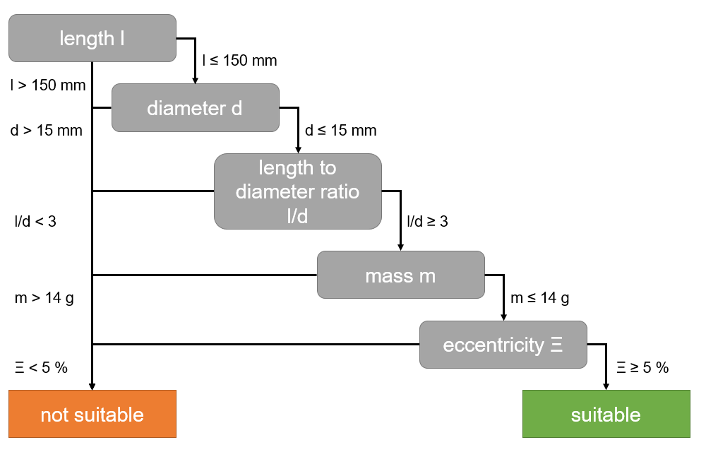
However, not every workpiece is suitable for aerodynamic feeding. Within the framework of the current research project, the match is therefore working on a catalog, which should make it possible to assess the suitability for aerodynamic feeding at a glance (see Figure 3). Important component-related criteria for a successful feeding process are the length, the diameter, their ratio, the mass and the center of gravity position. Using these criteria, potential users can assess the potential of aerodynamic feeding technology for their product range quickly and easily.
In order to categorize further properties of the components, the match is developing a model which simulates the behavior of different components in the aerodynamic orientation process. For the model, the differential equations of motion of the component as a function of the five plant parameters are established and solved numerically. By analyzing the calculated movement of the component due to the air impulse, it can be predicted whether or not the component is suitable for aerodynamic orientation. In addition, the simulation model will be used to predict the best system parameters in order to further reduce the adjustment time of the feeding system.
Equipped for the future
To make aerodynamic feeding technology more attractive for companies in the future, the match is working on new methods for an even more universal and flexible feeding system. For example, research is being conducted into how the adjustment of the system can be accelerated by using high-speed cameras in combination with machine learning methods while increasing reliability at the same time. In addition, the range of suitable components is to be expanded by implementing further aerodynamic actuators.
The aerodynamic feeding technology shall thus become an innovative alternative to conventional feeding technology and the existing deficits will be reduced.


