So far, cross-wedge rolling has been used to produce parts with round cross sections. IPH is working on making non-round cross-sections producible with special rolling dies. However, this makes the forming process much more complex, and the die geometries of the upper and lower dies must be precisely matched to each other and follow a complex geometry curve. Therefore, it is necessary to investigate hundreds of tool geometries in the research project “Unrundwalzen”. To save time, the creation of these geometries is automated.
Rolling of non-circular cross sections
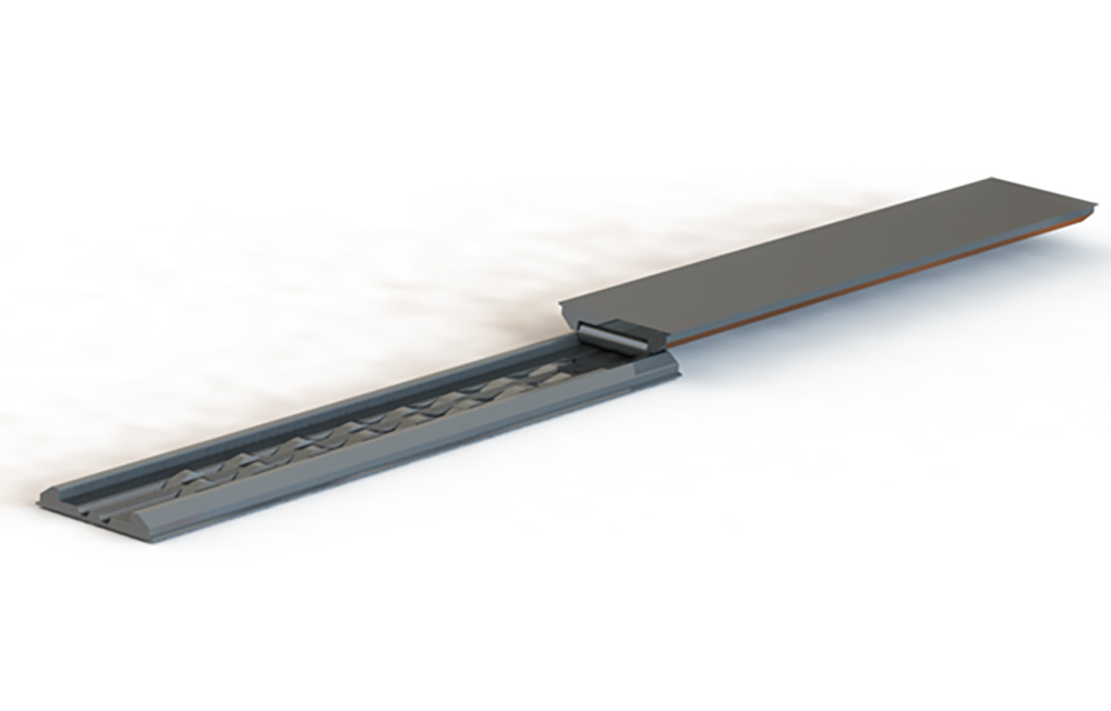
In the research project, FEM simulations are first used to investigate how locally non-circular cross sections (ellipse, eccentric, elliptical eccentric) can be rolled into a round billet. The rolling process is carried out with the aid of a pair of tools consisting of an upper and lower die (see Figure 1). The two halves of the tool move in opposite directions, thereby rotating the billet.
Depending on whether ellipses, eccentrics or elliptical eccentrics are to be rolled, different tool engravings are required in the upper and lower dies. In the research project, two non-circular forming elements offset from each other are rolled into the cylindrical billet. One form element would be, for example, a locally restricted ellipse or eccentric on the otherwise still round billet.
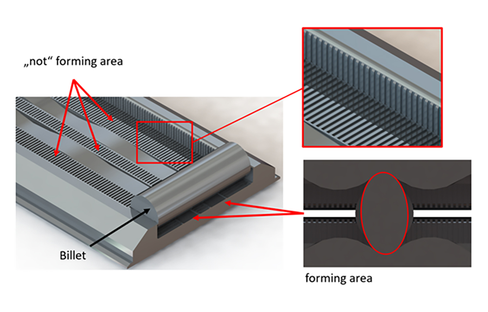
The tool pair takes this into account in the form of two tool engravings on a respective tool (see Figure 2). The wave engraving is defined here by a specifically adapted wave profile on the rolling tool. The non-forming area, i.e. that on which the cylindrical billet rolls, is called the web and is provided with grooves. The grooves are necessary in order to achieve not only a force fit but also a form fit during the rotation of the billet on the web. The geometry of the grooves can vary. The axial limitation of the stock flow is realized by die walls.
Non circular rolling depends on many parameters
Which parameters influence the rolling process – and how must the dies be designed so that unround rolling succeeds? To answer these questions, the researchers are investigating the following parameters:
- Width and strength of the engravings (higher length to width dimension of the ellipse, increasing eccentricities)
- Necessity of the central bar and its width (distance between the engravings).
- Dimensioning of the grooves in the bars and in the walls (groove width, groove depth, distance between the grooves)
- Length of the engraving (how many revolutions are available for the forming?)
- Forming speed and temperature
Because of the large number of different parameters, simulations with very many differently designed tools are necessary.
Algorithm reduces design effort
Designing the rolling dies to perform the parameter studies is a repetitive process and thus offers high automation potential. The development of the algorithm in SOLIDWORKS CAD software has helped to design the tools much faster – regardless of the person using them.
After the user has entered the parameter variation (see above), the algorithm constructs the upper and lower tools as well as the billet and positions them appropriately to each other in an assembly using links. The tools that have been matched to each other are automatically saved in an ordered form as a part, assembly and STL file.
The calculation of the tool engravings for the upper and lower tool is also automated. These engravings are imported by loading a text document into the SOLIDWORKS design interface. Only after the engraving is available to the algorithm does the design process begin. The design is thus based on the engravings, so that they form the foundation.
The generated assemblies can then be imported into FEM software. There, simulations are carried out with all the designed tools to find out with which parameter combinations the non circular rolling succeeds best.
Time saved by the algorithm
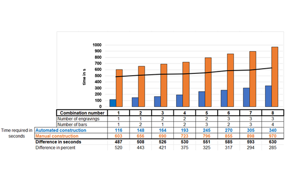
How much time does automated design save compared to manual design? To evaluate this, the researchers recorded the time it takes some experts to design tools. The number of lands and engravings were varied for each case. Time recording began when a blank part document was opened and ended after an assembly was completed.
The result (see Figure 3) for manual design is shown in orange, while that for automated design is shown in blue. The person designing remained the same and had previous design experience in SOLIDWORKS. The hardware and software also remained identical. The efficiency of the algorithm compared to the manual design is given by the difference in time (black curve) of the respective measurements. The result of this difference is given in absolute and percentage values.
It can be seen that the efficiency for the automated design – compared to the manual design – has increased between 285% and 520%. With regard to the absolute values, the efficiency increases in the course of the measurement the more forming elements a rolling die contains. This increases further the lower the level of knowledge of the person designing the tool.
Automated generation of modular tools
For future applications, the algorithm is to be extended to include the function of automatically generating assemblies in modular form that can be used in the real production environment. The tool should no longer consist of one piece, as shown in Figure 2, but of individual parts that are fixed to a base plate. This has the advantage that the rolling dies in flat die design no longer have to be made from solid material and that the die engravings can be exchanged or moved. The shape and displacement of the rolled-in form elements can thus be varied. This will facilitate the experimental investigations with different tools that IPH is planning following the parameter study.