Beside a shortmachining time and sufficient tool life, the reliable removal of chips is essential for cost-effective turning. If long chips are produced due to insufficient chip breaking, they cannot be reliably removed. There is a risk of damage to the tool, workpiece and machine. Moreover, the operator has to intervene manually, which increases the process time.
Aside from the material of the workpiece and a chip breaker on the tool, the geometry of the cross-section of the undeformed chip and in particular the chip thickness h is decisive for chip breakage. Among other things, this depends on the cutting edge angle κ, the feed f and the cutting depth ap.
The choice of a suitable cutting edge angle, together with the selected process parameters, is also decisive for tool life. The rule here is that large cutting edge angles and feed motions promote good chip breaking, while small cutting edge angles and feed motions reduce the specific cutting edge load and can therefore increase tool life.
Adapting the process to the workpiece geometry
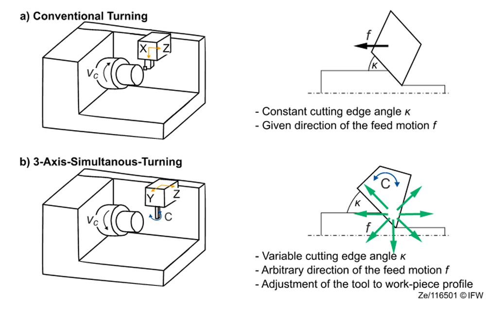
In conventional turning processes, the cutting edge angle is predetermined by the shape of the tool and therefore cannot be adapted to the engagement conditions during the process. With 3-axis simulated turning, however, the cutting edge angle can be influenced by rotating the milling spindle (see Figure 2). This makes it possible to vary the cutting edge angle during the process. This makes it possible to adapt the process to the workpiece geometry and to generate a suitable chip cross-section in terms of chip breaking and productivity.
Due to the complex tool movements and variable process parameters, it is not possible to determine the geometry of the cross-section of the undeformed chip . Due to this, the Institute of Production Engineering and Machine Tools (IFW) at Leibniz Universität Hannover, in collaboration with the company Ceratizit, has developed a numerical approach for determining the chip cross-section based on the institute’s own material removal simulation IFW CutS. This simulation can be used to determine the resulting chip cross-sections during turning and thus identify critical areasalready in the process planning stage (see Figure 3).
Improving chip breaking and reducing machining time
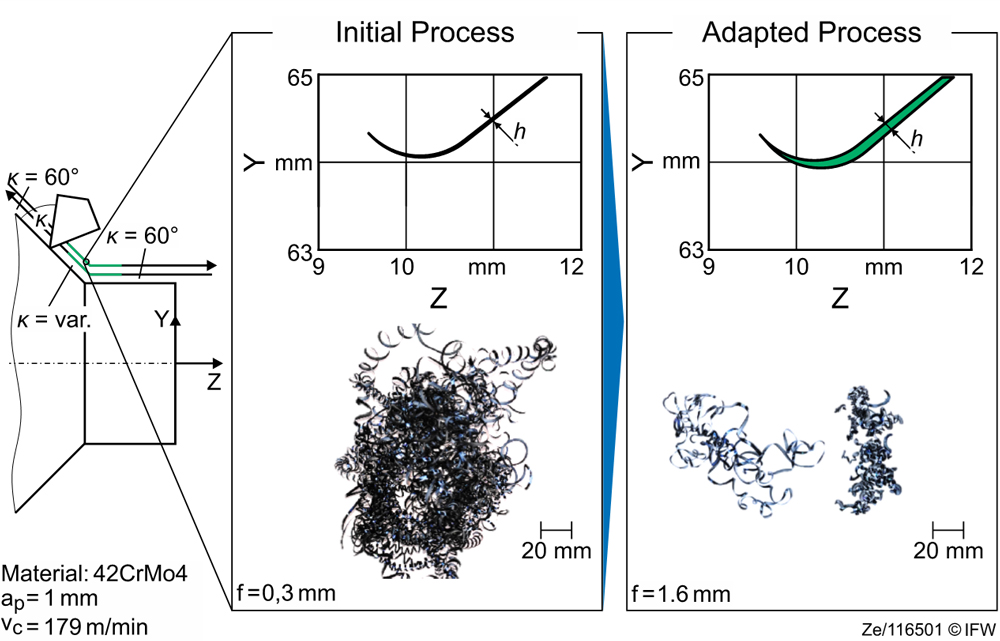
The successful application of this method was demonstrated in the machining of the material 42CrMo4. Here, a geometry consisting of a cylindrical and a conical surface was to be machined in a continuous cut in the spindle direction and against the spindle direction with a constant cutting edge angle of 60°. Since a sudden change in tool orientation is not possible, a transition between the two areas is necessary in which the cutting edge angle is adjusted by rotating the tool.
In the simulation, an unfavorable geometry of the cross-section of the undeformed chip with a very low thickness of the undeformed chip was detected in this area. During the process this would result in long, unbroken chips. By adjusting the feed, the effective chip thickness h* was increased from 0.015 mm to 0.078 mm and a significant improvement in chip breakage was achieved. In addition, the machining time of the process was reduced by 30 %.
The chip cross-sections in the transition areas depend, among other things, on the desired cutting edge angles, the geometry to be produced and the design of the transition. Both very small and very large thicknesses of the undeformed chip can occur, which is why a blanket adjustment of the feed does not make sense.
Machining complex contours with 3-axis simultaneous turning
Therefore3-axis simultaneous turning offers the possibility of achieving consistently good chip breaking and uniform tool loading, even for complex contours, through targeted coordination of the tool position and process parameters. Due to the large number of potentially occurring transitions, simulative approaches are a tool to optimize these transitions early during the process design and to avoid additional experimental investigations.
In a next step, the chip breaking behavior and the material-specific tool load for other materials and machining conditions will be investigated. The additional degree of freedom of the rotational movement also offers new possibilities for the use of locally different chip breakers, which should also be taken into account in the modeling of the tool.
The additional degree of freedom also offers new possibilities and challenges for the optimum design of roughing and finishing operations. In order to make full use of this additional degree of freedom, a simulation-supported path planning for a tool path optimized with regard to chip breaking and tool wear is therefore to be developed in the long term. In addition, investigations are planned to take into account varying material properties across the diameter in the material removal simulation.