Challenges in tool grinding
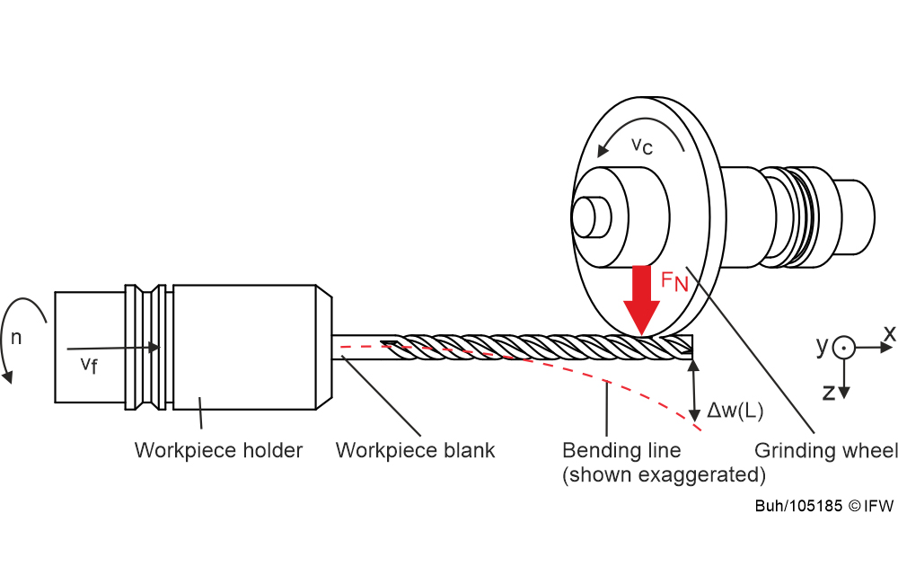
Flutes of solid carbide tools – for example twist drills – are produced by grinding with high depth of cut in a single over-grind, the deep grind. Due to the high depth of cut and high feed rate, a high force FN affects on the tool blank and pushes it away (see Figure 1). The workpiece therefore bends during machining. This results in a shape deviation, for example a core diameter that is too high, and scrap occurs.
To counteract the displacement Δw(L), a steady rest is used in industry to support workpieces with high length-to-diameter ratios (L/D > 8). However, setting up the steady rest requires a great manual effort, as the position of the steady rest must be manually adjusted for each workpiece geometry. Alternatively, the feed rate is reduced to reduce process forces – but this reduces productivity.
Sensory spindle to compensate for displacement
In order to manufacture in a resource-saving and productive manner, the Institute of Production Engineering and Machine Tools (IFW), in cooperation with VOLLMER WERKE Maschinenfabrik GmbH, researches online compensation of workpiece displacement during tool grinding.
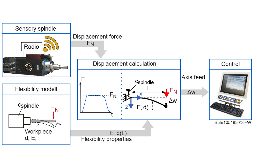
For this purpose, the IFW is developing a sensory grinding spindle to measure the radially acting displacement force FN during grinding. A flexibility model is used to calculate the displacement of the workpiece. The amount of displacement is then compensated for in the control system by means of online displacement compensation. (see Figure 2).
Challenges for determining the displacement
It is known that a tool clamped on one side behaves similar to a bending beam. Influencing variables on the displacement are the material-specific modulus of elasticity E, the cantilever length L and the area moment of inertia I.
During the machining of a tool blank, however, the area moment of inertia changes continuously because the flutes are added one after the other. The resulting high complexity in determining the resulting displacement can be represented by an ablation simulation, which incrementally calculates the current area moment of inertia. However, this requires considerable computing power, which makes it impossible to determine the displacement in real time.
Compensation of workpiece displacement
How can displacement compensation nevertheless be performed on a machine controller – even though exact calculation in real time is not possible? For this purpose, the researchers at IFW are developing a reduced mathematical model with an equivalent stiffness of the workpiece.
A simple spring-mounted bending beam is chosen as the model approach for calculating the workpiece displacement (see Figure 3). Due to the bearing, the stiffness of the spindle and the rest of the machine structure is taken into account for the calculation of the workpiece displacement Δw(L). To reduce the computational effort, the stiffness of the workpiece is modeled by the equivalent stiffness cWst,sub (see Figure 3, Equation 3).
The equivalent stiffness combines the modulus of elasticity and the area moment of inertia that changes during machining (see Figure 3, equations 1 and 2). The area moment of inertia depends on the cross section and thus on the effective diameter of the workpiece. In order to avoid the high calculation effort of the area moment of inertia by the material removal simulation, one-time experimental investigations are carried out. The aim here is to quantify the influences of the workpiece diameter and the L/D ratio in order to create a database for the approximation of the equivalent stiffness of the workpiece. In addition, the course of the flexibility under the influence of the area moment of inertia changing from flute to flute is determined.
Experimental investigation of workpiece flexibility
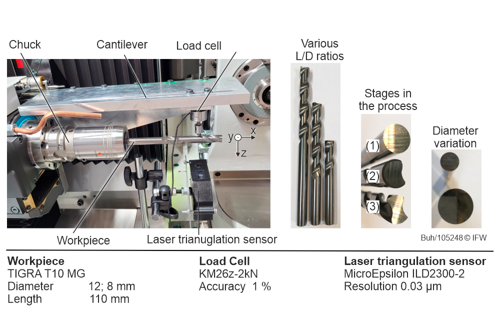
In order to determine the simplified mathematical description of the equivalent stiffness taking into account these influencing parameters, the clamped workpiece was loaded radially by a fixture at various positions along the x-axis (see Figure 4, left). At the force application point, the normal forces FN were detected with a load cell and the resulting displacement Δw(Lx) as a function of the load position Lx with a laser triangulation sensor. The flexibility d(Lx) was determined via the quotient of normal force and displacement. For this purpose, several drills with different L/D ratios (5.6 < L/D < 16.5) were statically loaded and the displacement was measured.
To investigate how the area moment of inertia changes as a result of machining, the researchers fabricated different machining stages of the drills (see Figure 4, right: no flute (1), one flute (2) and two flutes (3)) and also analyzed the displacement due to static loading.
Varying flexibility of long cantilevered workpieces
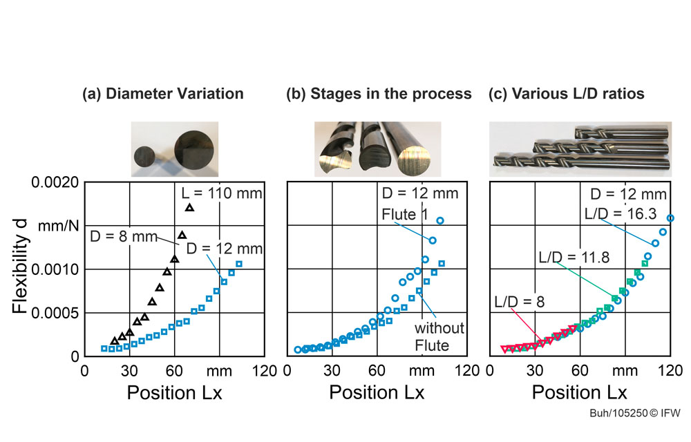
As an example, Figure 5 shows the results of the blanks with diameters of 8 mm and 12 mm. The results show that the flexibility of the workpiece increases progressively with increasing cantilever length and decreases with increasing diameter due to the increasing area moment of inertia (see Figure 5a).
The influence of the area moment of inertia changing as a result of machining on the workpiece flexibility is shown in Figure 5b as an example for diameter D = 12 mm. With increasing number of flutes, the flexibility increases due to the reduction of the area moment of inertia. This behaviour is also exhibited by the measurements with the diameter of 8 mm. It is clear that the flexibility increases and the gradient increases from flute to flute.
The flexibility of the three different L/D ratios (see Figure 5c), on the other hand, is not significantly affected by the projection length. The deviations between the three series of measurements are δ < 2 % and arise mainly from measurement uncertainties due to the alignment of the load cell and the laser triangulation sensor.
Simple mathematical model instead of complex simulation
The results of the investigation thus show that there is a steady progression of the flexibility as a function of the diameter and the L/D ratio as well as the area moment of inertia changing as a result of machining. The cantilever length, on the other hand, has no significant influence on the course of the workpiece flexibility.
This shows that the workpiece flexibility during tool grinding can be approximated by a simple mathematical approximation and does not have to be determined by an ablation simulation with a considerable computational effort.
Researchers at IFW develop prototype of the sensory spindle
In the future, the sensory spindle will be prototypically implemented. To expand the database of the approximation of the equivalent stiffness of the workpiece, further experimental investigations will be carried out with milling cutters with different numbers of teeth in order to transfer the model approach to milling cutters as well. Subsequently, the necessary parameters are identified for the model in order to be able to take into account different diameters and the changing area moment of inertia in a generally valid manner over the course of the process.