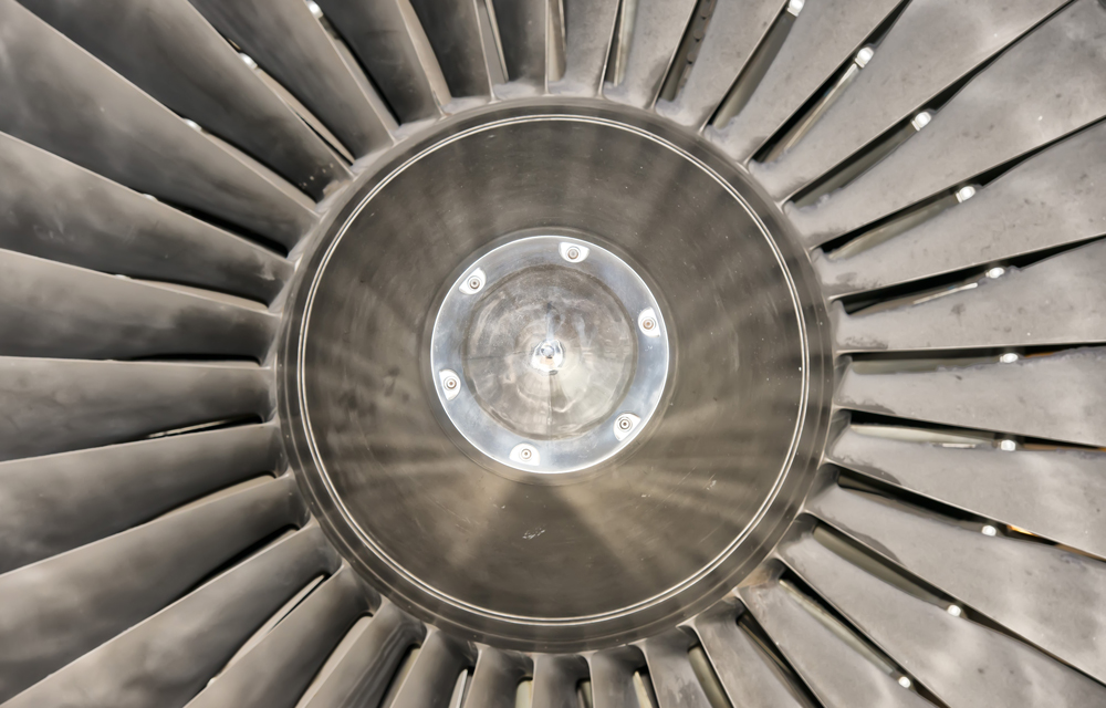
Whether in aircraft or gas turbines: Wherever high temperatures and stresses occur, high-temperature materials are needed. They are designed to withstand temperatures around 1000 °C and superimposed loads during operation. However, if these challenging conditions are applied over a long period of time, the materials start to creep.
Microstructure ensures durability
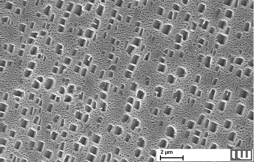
Nickel-based superalloys have excellent creep properties thanks to their special microstructure. They form a second phase (γ’-phase), which is mostly precipitated as cuboids and, depending on the volume fraction, is present in the matrix (γ-phase) like a brick wall. These additional phase boundaries curtail the movement of dislocations within the material and are thus the reason for the alloy’s mechanical strength at high temperatures.
However, even this microstructure changes due to creep. The γ´-precipitates tend to alter their shape, form a typical raft structure and merge together, reducing the strength of the alloys.
Material model for nickel-based alloys
The creep process depends on the alloy composition, temperature, load and duration. The influence of these parameters is being investigated by the IW in a joint project with the Institute of Continuum Mechanics (IKM) of Leibniz University Hannover.
The IKM integrates the findings of the IW into a three-dimensional material model in order to be able to predict the material behaviour of nickel-based alloys. After all, if the behaviour of the alloys under certain loads is known, the basic conditions and limits for their use can be defined more precisely, so that components can be used safely for as long as possible.
Creep tests
At the Institute of Materials Science, various methods are available to observe the microstructural evolution during creep until failure of the specimen with different spatial resolution. The challenge is that all investigations have to take place on the same sample surface in order to link the results. In addition, the investigations should preferably be located in the area of the crack that occurs when the specimen fails.
In order to investigate the creep processes in detail, the scientists at the IW carried out experiments with small samples of the nickel-based alloy IN738LC and applied different methods simultaneously to be able to identify alterations in the microstructure.
First, the scientists examined the initial state of the γ´-precipitates using a scanning electron microscope (SEM) and recorded the orientation of the grains using Electron Backscatter Diffraction (EBSD). To do this, the sample must be prepared metallographically, i. e. ground and polished very finely.
To be able to track the local strains of the sample, the scientists applied a special surface pattern. By employing Digital Image Correlation (DIC) an evaluation the local deformations is possible. Like the sample, this pattern also has to withstand the stresses and the temperatures during the creep test so that it can still be evaluated afterwards.
The tests were carried out at temperatures between 700 °C and 900 °C and stresses of up to 500 MPa. The scientists then prepared the sample again and examined it in the SEM.
The microstructure in 3D
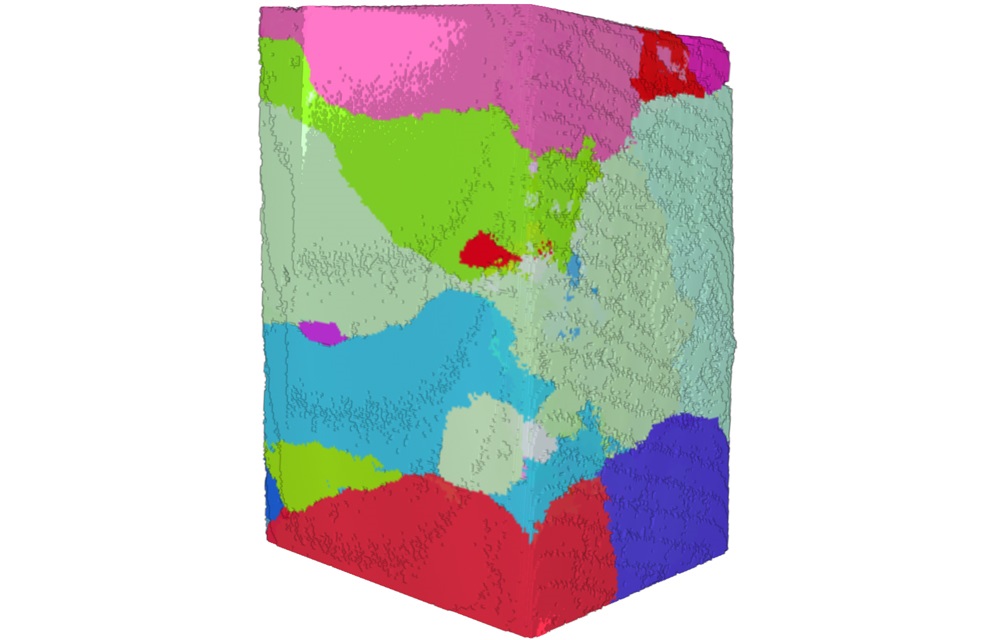
Because the material model that the researchers at the IKM are developing is intended to depict the changes in the microstructure in three dimensions, a three-dimensional characterisation of the microstructure is preferred. This possibility is provided by an X-ray microscope (XRM) available at the IW.
Not only can the XRM be used to compute a three-dimensional image of the crept specimen, but the orientation of the grains inside the material can also be displayed using Diffraction Contrast Tomography (DCT). Even if the resolution is lower than in the two-dimensional EBSD measurements, the DCT method offers further advantages in addition due to the three-dimensional representation. In particular, a metallographic sample preparation is not required and thus the risk of preparation artefacts is reduced. Furthermore, the measured data representing the 3D microstructure can easily be analysed by the IKM to parametrize the material model.