Cryogenic storage of tissue is an important tool for clinical research. It allows scientists to test new treatments for diseases and evaluate the effectiveness of those treatments.
From 2020 to 2023, the number of organic cellular material and other samples that need to be stored or processed within a cryogenic environment has increased significantly, due in large part to the global pandemic of the Sars Cov-2 virus (Covid-19). Both research into the virus and the development of a vaccine against the disease caused by the pathogen required technical advancements in the field of cryogenic storage in biobanks.
A frosty working climate
At the Institute of Assembly Technology (match) at Leibniz University Hannover, approaches to automating handling processes in biobanks for cryopreservation in the temperature range from -130 °C to -196 °C are therefore being researched. In general, cryopreservation refers to the freezing and storage of cellular materials at temperatures below -130°C. Cryopreservation thus allows biological cellular material to be stored for an almost indefinite period of time.
By automating the handling of samples within biobanks, the following problems can be circumvented:
- Unsafe sample handling (mechanical damage).
- Thermal sample damage due to heating or temperature fluctuations
- Limited working speed during manual handling
- Increased risk of specimen mix-ups
- No protective area when handling hazardous materials
Compliant joints for the robot
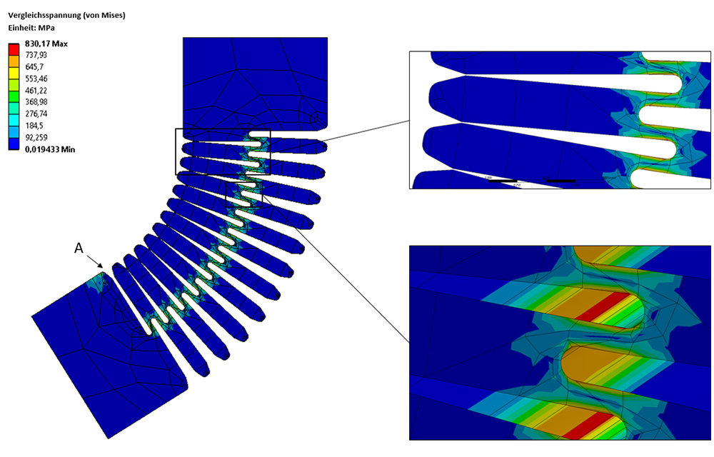
To realize a complete automation of handling operations in a storage container, a parallel robot with passive universal joints and with wireless power supply for the cryogenic gripper actuators is being developed at match. The cardan joints represent compliant mechanisms made of monolithic f. Their mobility is based only on the elastic deformation of certain areas (so-called thin sections) of the mechanisms. The challenge here was the low mobility of the monolithic joints compared to conventional swivel joints and the previously unexplored influence of low temperatures on their deformation flexure behavior. In comprehensive FEM simulations, solid-state joints with 27 deformable thin sections were determined to be optimal (see Figure 1). Eighteen of these joints are required in the overall structure of the parallel robot.
Frozen, but agile
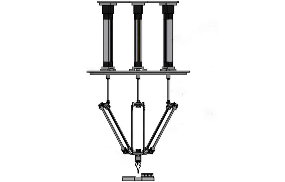
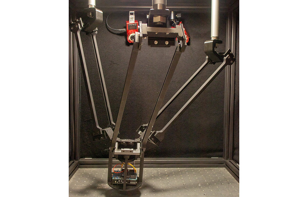
The overall structure of the parallel robot (see Figure 2 and Figure 3) consists of a total of three identical kinematic chains. These are arranged according to each offset at an angle of 120°. The kinematic chains are connected to the end effector platform at the lower end. At the upper end, the respective coupling rod is bolted to the associated piston rod of the linear actuator. These are mounted via plain bearings in the lid of the cryogenic vessel. The three linear actuators generate the translatory drive motion.
For testing in a pick-and-place process, two Micronic 96 sample racks and a barcode scanner for sample identification are set up in the lower area of the cryogenic container (see Figure 4 and Figure 5). This arrangement defines the workspace of the robot.
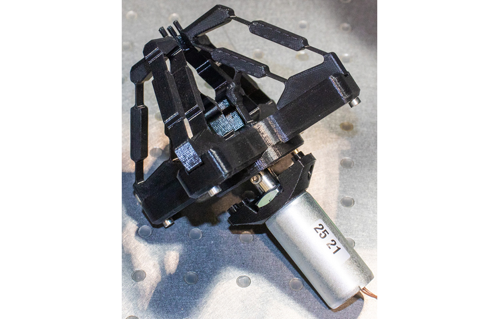
The entire robot structure has a moving mass of about 1800 g. The slim structure of the kinematic chains and the end effector thus ensure significantly higher dynamics of the system. The tip of the end effector is centered above the bearing racks loaded with sample tubes. The working area is a square of 200 x 200 mm. The end effector itself consists of a monolithic gripper with a compliant mechanism, an electromagnet as an actuator and integrated control electronics. The realized functional model operates energy-efficiently at low temperatures.
What’s next?
At match, research continues into the automation of handling processes. In the future, on the one hand, further monolithic grippers are to be developed for individual sample tubes (see Figure 6), but also for microtiter plates and entire sample racks. On the other hand, control and regulation mechanisms for the parallel robot will be designed, which take into account both the compliance of the construction and the influence of the extreme working temperatures. Optical position monitoring systems and motion-capturing concepts are also used here (see Figure 7).


