Whenever large quantities of bulk material need to be transported in a steady stream – for example, when transporting raw materials from the mining area to the loading station or to the port – belt conveyor systems are used. Only with them can such masses be moved continuously.
Idlers in belt conveyor systems
Idlers are a fundamental component of belt conveyor systems. Thousands of them are used to support and guide the belt and thus the bulk material. Idlers are based on a simple design with a standing axle and an idler shell supported on both sides. The bearings are protected from water and dust by a labyrinth seal on both sides between the idler shell and the idler axle.
The quality of an idler is largely determined by its running resistance. This is the force that has to be applied to the idler shell in order to drive the idler. This is caused by friction in the bearings and, in some cases, in the seals, as well as by the lubricant used. The idler running resistance accounts for a considerable proportion of the total resistance of a belt conveyor – usually between 5% and 15%, in some cases up to 30%. The idlers thus have a significant influence on the dimensioning of the drive and the energy consumption of the system.
Other factors influencing running behavior are concentricity and balance quality, the required breakaway torque and axial displaceability. These factors also have an indirect effect on running resistance and can lead to higher noise emissions and have a negative impact on the service life of idlers.
Idler test rig with climatic chamber
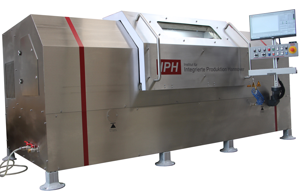
In order to be able to investigate the factors mentioned above that influence running behavior under different conditions, a test rig was developed at IPH. The test rig is the result of the research project “Practical characterization of the running behavior of driven and conventional bearing idlers for (bulk) conveying systems (EiLaT)”.
The heart of this test rig is a climatic chamber in which all measurements are carried out. In this climate chamber, the temperature can be set to values from -40 °C to 60 °C and a relative humidity of up to 100 %. This is important because idlers are often used all over the world in very harsh conditions. The simulation of the different environmental conditions is made possible by a cooling unit, a heating coil and an evaporator.
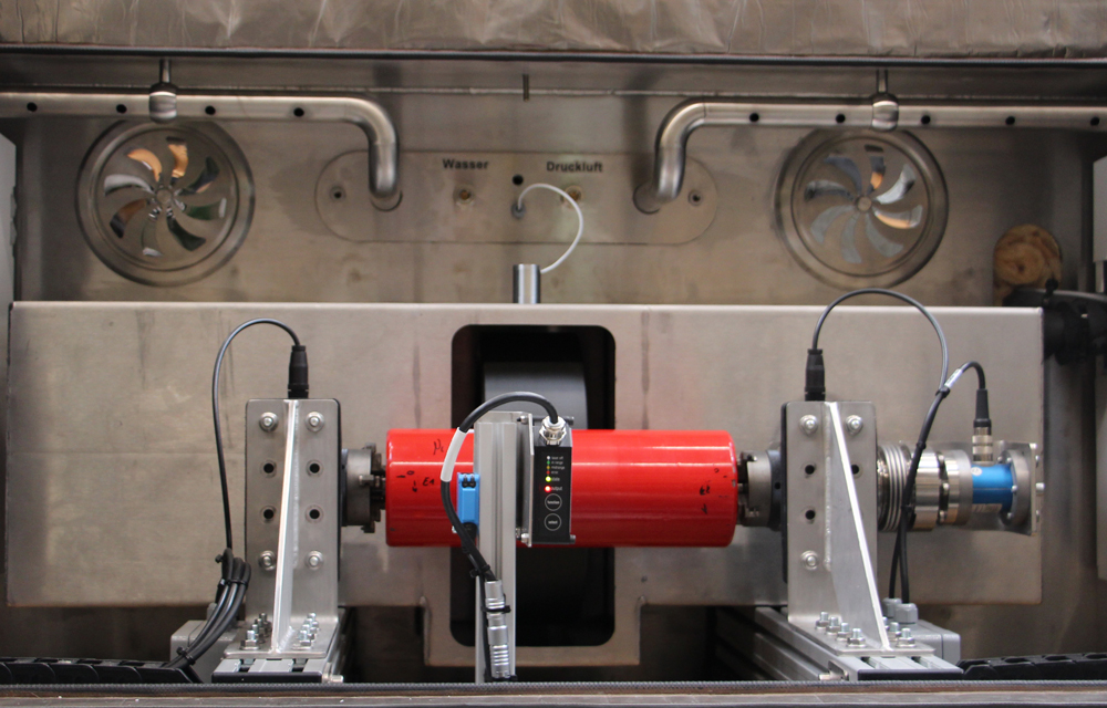
The idler to be tested is mounted in the climatic chamber with the idler axle in two movably mounted ring chucks. A drive wheel mounted on a movable carriage drives the idler. The carriage, and thus the drive wheel, is pressed against the idler with a defined force by an electromechanical cylinder. This simulates the load on the idler during operation and can be up to 3 kN.
Various sensors are arranged around the idler to measure the factors influencing the running behavior. The torque transmitted to the idler axle is recorded via a torque sensor on the right-hand bearing. The running resistance can be calculated from this. With the aid of acceleration sensors mounted on the bearings and a light barrier, the balance quality of the idler can be determined. A laser triangulation sensor is used to measure the geometry of the idlers in order to determine concentricity deviations.
Motor-driven idlers on the test rig
Driven idlers are a trend-setting development. To support this development, the idler test rig is designed as a dual measuring device so that driven idlers can also be tested. Driven idlers have their own electric motor inside, which sets the idler shell in motion and transfers the energy to the belt.
On the idler test rig, the driven idler is operated at a defined speed. The drive wheel of the test rig is pressed against the driven idler with a defined force and the drive wheel brakes it with a counter-torque. The influencing factors of load, speed and counter-torque can be varied. Of particular interest is the starting behavior of the idlers under different conditions.
IPH can support manufacturers and research institutions in the development of driven idlers with the idler test rig.
Tightness against dust and water
Another new development at IPH is the test rig for investigating the water and dust tightness of idlers. The ingress of water or dust has a negative impact on the running behavior and service life of idlers.
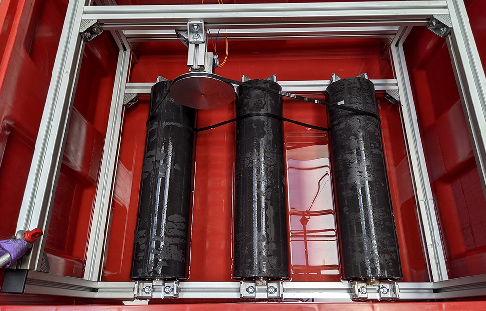
DIN 22112-3 specifies the procedure for these tests. Three idlers run for 96 hours in a container filled with water up to the height of the axle for the water tightness test. The amount of water that penetrates the idlers is examined. For this purpose, the idlers are weighed before the test and after 24 hours to determine the amount of water that has penetrated. After the test, the idlers are stored for ten days and then disassembled and visually inspected for corrosion and loss and contamination of lubricant.
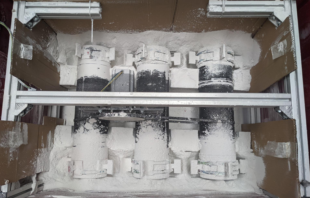
For the investigation of the tightness against dust penetration, three idlers run in a container with test dust. Small vanes are attached to the idlers to swirl the dust. After 96 hours of continuous running, the test is completed. The idlers are disassembled and it is determined how much dust has penetrated.
By setting up a test rig with an electric motor and drive belt, IPH is now able to perform this test, which is important for the running behavior and service life of idlers.


